A Closer Look at Clarence Barlow's ISIS
In 2005, Clarence Barlow published a paper on Intra-Samplar Interpolating Sinusoids (ISIS), an audio analysis-synthesis algorithm. It did not make much of a splash, with the paper having only 7 citations in Google Scholar. Nevertheless, it produces some interesting sounds, so let’s dive into it.
First, some context. The precursor to ISIS is a technique Barlow calls spectastics. In this method, the short-time Fourier transform is computed of an audio signal, and at each frame, the magnitude spectrum is resampled logarithmically to 12EDO and used as a probability distribution to select a pitch. The pitch sequence forms an extremely rapid melody, which can be synthesized or played on a robotic instrument. Barlow describes the spectasized melody as “remarkably like the original sound recording.”
In ISIS, this concept is taken to an extreme by making the “melody” a constant amplitude sine wave whose frequency is changed every sample. Given a digital signal that doesn’t exceed ±1, we can interpolate between any two successive samples with a partial cycle of a sine wave. An image helps here; the dots show the sampled digital signal.
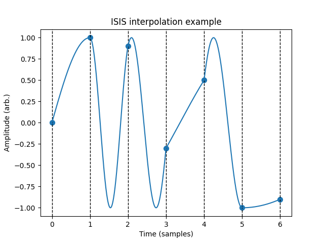
For example, if the samples are 0 and 1, as seen in the first two samples in the image, we can interpolate with a quarter sine wave with a period of 4 samples and a frequency of 1/4th the sample rate. There are actually infinitely many ways to do this interpolation. For example, from 0 to 1 we can also have a sine wave that completes 5/4ths of a cycle. We can even assume that the initial phase of the sine wave is \(\pi\) and the final phase \(5\pi/2\), or have the sine wave going backwards with phase ramping from 0 to \(-3\pi/2\).
To resolve the ambiguity, ISIS restricts the frequency to be always nonnegative so the phase never goes backward, and always assumes the phase at every sample point is in the range \([-\pi/2, \pi/2]\) modulo \(2\pi\). There are other approaches, such as picking the minimum possible nonnegative frequency or the frequency of minimum absolute value, which may produce interesting alternative sounds. I won’t get into these (this is a relatively low-effort post), but feel free to try them out.
Definition
Barlow’s formulas actually have a mistake, taking the logarithm of a signal that can range into negative values. The signal first needs to have a modulo 1 operation applied to it. Second, converting the frequency signal to logarithmic isn’t even necessary in the first place. To correct for these issues, the presentation of the algorithm is modified here for clarity, but the sounds should be faithful to the original. (Also, what’s up with the weird symbol he uses for sample rate? Looks like a combination of the letters “S” and “R”? What’s wrong with \(f_s\)?)
ISIS takes a signal \(|x[t]| \leq 1\). The analysis process is
and resynthesis is
where \(\text{frac}(x) = \text{mod}(x,\,1) = x - \lfloor x \rfloor\) where \(\lfloor x \rfloor\) rounds to negative infinity.
The frac operation in the second equation is not theoretically necessary due to the periodicity of the sine function, but \(z[t]\) will lose floating-point precision if allowed to approach infinity, and degradation will be plainly audible after a few seconds. Which, I mean, hey, if you’re into that, sure?
I was first learning to program SuperCollider UGens in C++ when I found out about ISIS, and promptly made it into two UGens. I now realize that this algorithm can be written with existing UGens in just three lines:
(
{
    var sig;
    sig = /* Define input signal here */;
    sig = sig.asin;
    sig = ((sig - Delay1.ar(sig)) / 2pi) % 1;
    /* Process analyzed signal here */
    sig = (Phasor.ar(DC.ar(0), sig, 0.0, 1.0) * 2pi).sin;
    sig ! 2;
}.play(fadeTime: 0);
)
The above code snippet is in the Public Domain, Creative Commons Zero, Guaranteed Lawyer-Free. Note the use of Phasor instead of Integrator; Phasor without an input trigger is like an Integrator with an inbuilt modulo. If we were to use Integrator followed by a modulo, we would run into the precision problem described above.
ISIS effects
As long as the input signal does not peak outside ±1, ISIS is lossless; it achieves perfect reconstruction for all signals. This can be verified easily from the above equations. Of course, the fun part is messing with the analyzed signal prior to resynthesis.
Pitch shifting
\(y[t]\) is thought of as a frequency signal, so our first thought might be to multiply it by a constant \(k\), as an abstract sort of “pitch shifter.” Let’s try pitch shifting a 100 Hz sine wave and increasing \(k\) from 1 to 2:
Curiously, if \(k\) is an odd integer, the ISIS pitch shifter actually produces a sine wave whose frequency is multiplied by \(k\). For all other \(k\), the effect sounds nothing like a standard pitch shifter, and more like a really weird distortion unit.
In general, if the input signal is periodic, the output signal of a pitch shifter will roughly retain that periodicity. It may be interesting as a guitar pedal.
Values of \(k\) extremely close to 1 such as 1.001 seem to produce rapid amplitude modulation effects. I tried applying ISIS pitch shifting to complex polyphonic signals, but pitch shifting turned them into a wall of noise!
Frequency shifting
Frequency shifting is accomplished by adding an offset to \(y[t]\). Note that adding 1 does nothing due to the frac function. Here’s a 100 Hz sine wave with an offset gradually increasing from 1 to 2:
Filtering
The effect of lowpass filtering \(y\) is hard to describe. Here’s a 100 Hz sine wave with a lowpass on the frequency signal opening from 100 Hz to 16000 Hz:
The lowpass seems to have the opposite effect one might expect. Lower cutoffs produce more high-end fizz, and higher cutoffs are more muted. Go figure.
The frequency signal has a range of 0 to 1, so when highpass filtering \(y\), it makes the most sense to first subtract 0.5 from the signal, perform the highpass, then add 0.5 back in. Here’s a 100 Hz sine wave with a highpass sweeping from 1 Hz to 16000 Hz:
FM
There are two ways to do FM here. Linear FM adds an oscillator to the frequency signal, while exponential FM multiplies by one. Below are 100 Hz sine waves with randomly modulated linear and exponential FM, respectively:
ISIS as a filter
Although presented as an analysis/resynthesis technique, ISIS is really a chain of stateless nonlinearities and standard linear filters. (As they say, everything is a filter.) In particular, the chain is:
arcsine nonlinearity → differentiator → wrap nonlinearity → [arbitrary processing] → integrator → sine nonlinearity
The arcsine and sine nonlinearities cancel each other out, as do the differentiator and integrator. The wrap nonlinearity is the odd one out, as it doesn’t have a corresponding inverse operation. If the analyzed signal is passed through unharmed, the wrap does nothing due to the periodicity of the sine function, but if the analyzed signal is modified, the wrap has a pretty big impact on the sound. It is possible to run ISIS without the wrap nonlinearity, but the effects above are a lot less interesting by comparison.
We can try to gain a better understanding of ISIS by imagining what happens with small signals close to 0. The arcsine becomes linear, the differentiator cuts dc and low frequencies with a +6 dB/octave slope, and the wrap nonlinearity effectively inverts, amplifies, and clips the signal into a 1-bit pulse wave. The integrator boosts the lows again with a -6 dB/octave slope, turning the pulse wave into a triangle wave. Finally, the sine nonlinearity acts as a wavefolder.
With this view in terms of traditional filters in mind, some of the transformations described above begin to make more intuitive sense. Multiplication of the frequency signal corresponds to driving the wavefolder harder. Addition by a constant turns into a ramp when integrated, so it’s identical to adding a saw wave to the signal prior to wavefolding. Linear FM is simply adding a signal in prior to the nonlinearity, and exponential FM is effectively amplitude modulation. I don’t have a good analysis for the effects of EQ filters, however.
Conclusion
Please don’t put me on a list.