TopMod, Blender, and Curved Handles
I’ve been working on a big project using Blender. More on that in a future post, but here’s a preview. The project has gotten me into a 3D art headspace, and I took a detour recently from this major project to work on a small one.
Blender isn’t my first exposure to 3D. When I was a kid, I played around a lot with POV-Ray – an outdated program even back when I was using it, but still a fun piece of history. I also found out about something called TopMod, which is an obscure research 3D modeling program. I was interested in it primarily because of Bathsheba Grossman, who used it in a series of lovely steel sculptures based on regular polyhedra.
The core idea of TopMod is that, unlike other 3D modeling programs, meshes are always valid 2-manifolds, lacking open edges and other anomalies like doubled faces. This is ensured with a data structure called the Doubly Linked Face List or DLFL. In practice, TopMod is really a quirky collection of miscellaneous modeling algorithms developed by Ergun Akleman’s grad students. These features give a distinctive look to the many sculptures and artworks made with TopMod. I identify the following as the most important:
Subdivision surfaces. TopMod implements the well-known Catmull-Clark subdivision surface algorithm, which rounds off the edges of a mesh. However, it also has a lesser known subsurf algorithm called Doo-Sabin. To my eyes, Doo-Sabin has a “mathematical” look compared to the more organic Catmull-Clark.
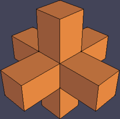
Original mesh.
Catmull-Clark subdivision surface.
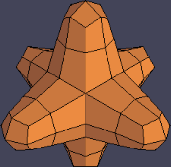
Doo-Sabin subdivision surface.
Rind modeling. This feature makes the mesh into a thin crust, and punches holes in that crust according to a selected set of faces.
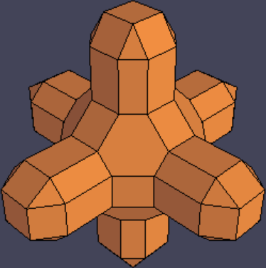
Original mesh with faces selected.
After rind modeling.
Curved handles. In this tool, the user selects two faces of the mesh, and TopMod interpolates between those two polygons while creating a loop-like trajectory that connects them. The user also picks a representative vertex from each of the two polygons. Selecting different vertices allows adding a “twist” to the handle.
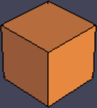
Original mesh.
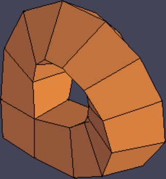
Handle added.
The combination of these three features, as pointed out by Akleman et al., allows creating a family of cool-looking sculptures in just a few steps:
Start with a base polyhedron, often a Platonic solid.
Add various handles.
Perform one iteration of Doo-Sabin.
Apply rind modeling, removing contiguous loops of quadrilateral faces.
Perform one or more iterations of Catmull-Clark or Doo-Sabin.
(I would like to highlight step 3 to point out that while Doo-Sabin and Catmull-Clark look similar to each other in a final, smooth mesh, they produce very different results if you start manipulating the individual polygons they produce, and the choice of Doo-Sabin is critical for the “TopMod look.”)
TopMod has other features, but this workflow and variants thereof are pretty much the reason people use TopMod. The program also has the benefit of being easy to learn and use.
The catch to all this is that, unfortunately, TopMod doesn’t seem to have much of a future. The GitHub has gone dormant and new features haven’t been added in a long time. Plus, it only seems to support Windows, and experienced users know it crashes a lot. It would be a shame if the artistic processes that TopMod pioneered were to die with the software, so I looked into ways of emulating the TopMod workflow in Blender. Let’s go feature by feature.
First we have subdivision surfaces. Blender’s Subdivision Surface modifier only supports Catmull-Clark (and a “Simple” mode that subdivides faces without actually smoothing out the mesh). However, a Doo-Sabin implementation is out there, and I can confirm that it works in Blender 3.3. An issue is that this Doo-Sabin implementation seems to produce duplicated vertices, so you have to go to edit mode and hit Mesh -> Merge -> By Distance, or you’ll get wacky results doing operations downstream. This may be fixable in the Doo-Sabin code if someone wants to take a stab at it. Also worth noting is that this implementation of Doo-Sabin is an operator, not a modifier, so it is destructive.
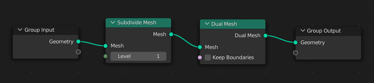
EDIT: Turns out, Doo-Sabin can be done without an addon, using Geometry Nodes! This StackExchange answer shows how, using the setup in the image below: a Subdivide Mesh (not a Subdivision Surface) followed by a Dual Mesh. The Geometry Nodes modifier can then be applied to start manipulating the individual polygons in the mesh.
Rind modeling can be accomplished by adding a Solidify modifier, entering face select mode, and simply removing the faces where you want holes punched. An advantage over TopMod is that modifiers are nondestructive, so you can create holes in a piecemeal fashion and see the effects interactively. To actually select the faces for rind modeling, TopMod has a tool to speed up the process called “Select Face Loop;” the equivalent in Blender’s edit mode is entering face select mode and holding down Alt while clicking an edge.
Curved handles have no equivalent in Blender. There is an unresolved question on the Blender StackExchange about it. To compensate for this, I spent the past few days making a new Blender addon called blender-handle. It’s a direct port of code in TopMod and is therefore under the same license as TopMod, GPL.
My tool is a little awkward to use – it requires you to select two vertices and then two faces in that order. TopMod, by comparison, requires only two well-placed clicks to create a handle. I’m open to suggestions from more experienced Blender users on how to improve the workflow. That said, this tool also has an advantage over TopMod’s equivalent: parameters can be adjusted with real-time feedback in the 3D view, instead of having to set all the parameters prior to handle creation as TopMod requires. The more immediate the feedback, the more expressive an artistic tool is.
Installation and usage instructions are available at the README. blender-handle is 100% robust software entirely devoid of bugs of any kind, and does not have a seemingly intermittent problem where sometimes face normals are inverted.
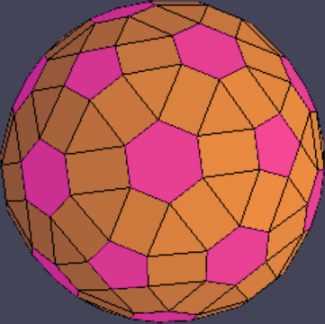
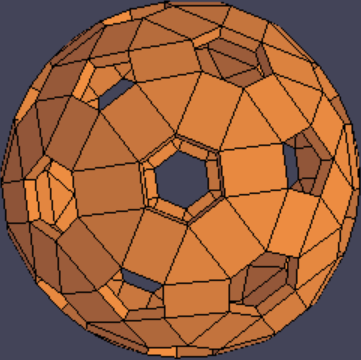
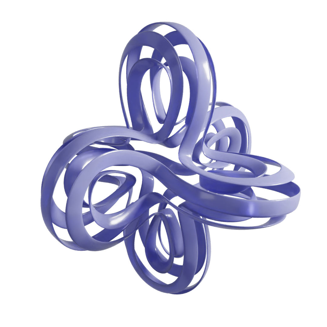
The rest of this post will be a nerdy dive into the math of the handle algorithm, so I’ll put that after the break. Enjoy this thing I made in Blender with the above methods (dodecahedron base, six handles with 72-degree twists, Doo-Sabin, rind modeling, then Catmull-Clark):
Description of the handle algorithm
The paper introducing the curved handle algorithm is “Interactive Construction of Multi-Segment Curved Handles” by V. Srinivasan, E. Akleman, and J. Chen, published 2002. The paper is worth a read, but while I was porting the TopMod code I found it was missing some details. As a result, I’m using this space to describe the full algorithm unambiguously. I’ve tried to make my addon code readable and well-commented, but it doesn’t hurt to describe it in prose also.
As an overview, the algorithm produces cross sections of the handle by varying a parameter \(0 \leq t \leq 1\), where \(t = 0\) produces face 1 and \(t = 1\) produces face 2. A cubic Hermite spline is used to interpolate between the centroids of the two faces, with the derivatives of the spline at the endpoints determined by the normals. The polygonal faces are assumed approximately planar and projected into 2D, converted to polar coordinates, and linearly interpolated.
Let \(\mathbf{c}_1\) and \(\mathbf{c}_2\) be the centroids of the two faces, and let \(\mathbf{n}_1\) and \(-\mathbf{n}_2\) be the normals. Then the centroid of the handle’s cross section at time \(t\) is:
where \(w_1\) and \(w_2\) are scalar “weight” parameters, and \(H_1(t) = 2t^3 - 3t^2 + 1\) and \(H_2(t) = t^3 - 2t^2 + t\). From the values and derivatives of \(H_1\) and \(H_2\) each at 0 and 1, it can be seen that \(\mathbf{c}(t)\) starts at \(\mathbf{c}_1\) and ends at \(\mathbf{c}_2\), and \(\mathbf{c}'(0) = w_1 \mathbf{n_1}\) and \(\mathbf{c}'(1) = w_2 \mathbf{n_2}\). \(w_1\) and \(w_2\) control how much the handle sticks out according to the normals. If they are zero the handle is perfectly straight, if they are both negative a tunnel is produced instead of a handle, and if they are opposite signs then you can make a nonorientable “handle-tunnel” like in a Klein bottle.
\(\mathbf{c}(t)\) gives us the centroid of the intermediate polygons that form the cross sections of the handle. \(\mathbf{c}'(t)\) gives us a normal vector of the plane in which the intermediate polygon at \(t\) falls. With these defined, what remains is to show how to interpolate between the two polygons.
A face is defined as 1. a circular list of 3D vertex coordinates, and 2. a normal vector. So that the user can control the amount of twist to the handle, each face’s vertex list has one designated as a “reference vertex.” We will assume temporarily that the faces have the same number of sides, but we’ll fix that later.
The first steps involve some normalization. First, we reverse the vertex list of face 2 and flip its normal vector (that’s why I wrote \(-\mathbf{n}_2\) above). We cyclically permute the vertex lists so that each list’s first entry is its reference vertex. Each face is then translated so that its centroid is at the origin.
The next step is to rotate the two faces so their normals are identical, and if the faces are approximately planar then they will be in a shared plane called the rotation plane. The vector \(\mathbf{r} = \text{normalize}(\mathbf{c}_2 - \mathbf{c}_1)\) is orthogonal to the rotation plane; I’m not totally sure why they chose this, and not clear on whether it actually matters which plane you choose. Anyway, to rotate face 1 so that its normal \(\mathbf{n}_1\) now becomes \(\mathbf{r}\), the axis of rotation is \(\mathbf{a} = \mathbf{n}_1 \times \mathbf{r}\). The angle of rotation is the angle \(\phi\) between \(\mathbf{n}_1\) and \(\mathbf{r}\). \(\arcsin ||\mathbf{a}||\) works, but only if \(0 \leq \phi \leq \pi / 2\). A more general formula is \(\phi = \text{atan2}(||\mathbf{a}||, \mathbf{n}_1 \cdot \mathbf{r})\). Face 2 is rotated by the same process.
Next, we set up a 2D Cartesian coordinate system in the rotation plane such that every point \(a\mathbf{x} + b\mathbf{y}\) on the plane is given by a pair \((a, b)\). Any two unit vectors orthogonal to each other and to \(\mathbf{r}\) will do, so we can use one of the edges of face 1 as \(\mathbf{x}\) and normalize \(\mathbf{r} \times \mathbf{x}\) to produce \(\mathbf{y}\). We then project each 3D polygon onto the rotation plane; the 2D coordinates of point \(\mathbf{p}\) can be computed as \(a = \mathbf{p} \cdot \mathbf{x}\) and \(b = \mathbf{p} \cdot \mathbf{y}\). The pair \((a, b)\) is then converted into polar coordinates \((r, \theta)\).
Now each vertex list is a sequence of polar coordinates. As the faces are assumed to have the same number of sides, linear interpolation can be performed individually on the radii and angles. The angles, however, require preprocessing to avoid artifacts caused by the wraparound at \(2\pi\). For face \(i \in \{1,2\}\), we have a sequence of angles \(\theta_1^{(i)}, \theta_2^{(i)}, \ldots, \theta_n^{(i)}\). We want this sequence to be nondecreasing, so for each pair \(\theta_k, \theta_{k + 1}\) we add \(2\pi\) to the latter until \(\theta_{k + 1} \geq \theta_k\). Furthermore, \(\theta_1^{(2)} - \theta_1^{(1)}\) should not exceed \(\pi\), or the handle will appear excessively twisty – if this is the case, subtract \(2\pi\) from all \(\theta_k^{(2)}\). Finally, if the user does want extra 360-degree twists, an integer multiple of \(2\pi\) may be added to face 2’s angles. With these transformations, the two sequences of angles can be linearly interpolated. The result is a new list of polar coordinates for each \(t\).
As the last step, we reconstruct the 3D polygon from these polar coordinates by going through the transformation steps backwards and inverse. We convert these polar coordinates into Cartesian coordinates \((a, b)\) and use the linear combination \(a\mathbf{x} + b\mathbf{y}\) to get 3D points. We then use an axis-angle rotation as before to rotate \(\mathbf{r}\) to the intermediate normal \(\text{normalize}(\mathbf{c}'(t))\). Add the resulting points to the centroid \(\mathbf{c}(t)\), and you have a cross section. Connect all the cross sections together with quadrilaterals, and that’s a handle!
Sorry, one more thing. If the two polygons have a different number of sides, you’ll have to do an additional step somewhere to make them match. TopMod seems to just chop off the extra vertices from the larger polygon; I prefer to take one vertex from the smaller polygon and repeat it until the polygons match. Smarter algorithms that are aware of the polar coordinates of the vertices are possible. Also note that some triangles will be necessary in place of quadrilaterals when connecting the vertices.
Variations can be easily conceived:
TopMod has a “pinch” feature where each cross section of the handle is uniformly scaled about its centroid by a function of \(t\) that starts and ends at 1. This allows making the handle thinner or thicker towards its midpoint. Weirdly enough, although this feature works in the Windows build of TopMod, the code path that implements it seems to be bypassed (the arguments that control the pinch are not passed in).
The handle can self-intersect if the weights are too small compared to the size of the faces. The pinch feature was likely designed to allow compensation for this, but could self-intersection be detected and countered automatically?
If the weight values are fixed, the handle construction is not scale invariant, which might be a nuisance for users working on objects with different levels of detail. The weights could be scaled by a factor depending on the sizes of the faces and the distance between their centroids.
Could the lengths of the segments be made more even?
What alternatives to a cubic Hermite spline look good?